
Why HP + UFH is the Most Efficient Combination
Tools & Aids
- →Pipe wrench or water pump pliers (for G 1" connections)
- →PTFE thread seal tape (min. 12 layers)
- →Hand pressure pump for pressure testing (0–6 bar, integrated manometer)
- →Bleed key or flat screwdriver for bleed valves
- →Spirit level (for horizontal alignment of the manifold)
- →Dowel & Screws (M6, for distribution box wall mounting)
Requirements: What your system needs to have
- →Set manifold position: max. 20 m from the boiler/HP, central to all heating circuits — minimizes pipe lengths and pressure loss
- →Pre-run sensor in the supply pipe present or planned? (mandatory for boiler control)
- →All underfloor heating pipes laid and accessible? Only install after screed installation and drying phase
- →Wall niche chiselled out for flush-mounted box, or wall surface cleared for surface-mounted installation
- →230V power within reach for actuators and room thermostat cables (if desired)
Manifold for heat pump: Hydraulic diagram, settings & funding
The combination of a heat pump + underfloor heating is the most efficient heating technology for new buildings and energetically renovated old buildings. The heating circuit distributor is the link between the heat pump and the surface heating system — if it is incorrectly sized or set, it significantly reduces efficiency.
(vs. 55 °C for boiler)
Optimal for HP efficiency
vs. radiator system
System diagram: Heat pump with heating circuit distributor
Inverter-controlled
circuit
Hydraulic separator
circuit
distributorStainless steel DN 25
Flow meter per circuit
Ø 16–20 mm
Screed/Dry
Requirements for the distributor in HP operation
| Property | Requirement for HP | Why? |
|---|---|---|
| Material | Stainless steel V2A (1.4301) | HP generates slightly acidic condensate (pH 6.5–7.2) — brass corrodes |
| Flow temperature | 30–45 °C (design) | The lower the flow temp., the higher the HP's COP (each K saves ~2.5%) |
| Set spread | 5 K (not 10 K!) | HP optimal with small spread: 5 K instead of 10 K → higher volume flow → better HP efficiency |
| Pipe spacing | 10–12 cm | More heating surface → lower flow temp. possible |
| Flow meter setting | Higher volume flow needed | 5 K spread = double volume flow vs. 10 K → open flow meter accordingly |
| Hydraulic balancing | Mandatory — GModG § 60 | Without balancing: HP runs inefficiently, KfW 458 funding is forfeited |
| Buffer tank/separator | Recommended (50–200 L) | Prevents HP cycling, extends lifespan |
Optimally adjust distributor for HP
HP flow e.g. 35 °C → return should measure 30 °C. Open flow meter per circuit until return temperature rises (more flow = smaller spread).
Formula: V̇ = Q / (c × ρ × 5 K). Example: 600 W room → 103 l/h target flow. Adjust flow meter accordingly.
Set HP heating curve (flow temperature depending on outside temperature) flat: gradient 0.5–0.8. The better insulated the building, the flatter.
Hydraulic balancing is mandatory for KfW-458 proof. Perform yourself with a flow meter distributor, keep the log — no specialist company necessary.
- Basic funding: 30% of eligible costs (max. €30,000 cost basis)
- Climate speed bonus: +20% for replacing an oil/gas heating system before 2030
- Income bonus: +30% for households with annual income under €40,000
- Combination possible: up to 80% total funding rate achievable
- Application via KfW Federal Funding, BAFA supplementary application for remaining costs
Heat pump + UFH distributor: What applies to DACH
In Germany, heat pumps will be de facto mandatory for new builds from 2026 (GModG requirements for EE share). In Austria, § 19 OIB-RL 6 applies, and in Switzerland, BAFU supports through cantonal programs. The heating circuit distributor as a central component of the low-temperature system must be dimensioned according to EN 1264-4 in all DACH countries.
- →Step 1: Fit distribution box into wall recess, align horizontally, and secure with anchors
- →Step 2: Screw ball valves (flow top / return bottom) to manifold with PTFE tape
- →Step 3: Insert distributor into the box, snap retaining clips into place
- →Step 4: Connect the underfloor heating pipes (flow and return) sequentially to the manifold connections – label the circuits!
- →Step 5: Slowly fill the system with water via the ball valve, bleeding all circuits individually
- →Step 6: Carry out pressure test with hand pressure pump at 6 bar for 30 minutes — no pressure drop = sealed
- →Step 7: Screw actuators (E30NC-230) onto all manifold outlets, lay cables to room thermostats
- →Step 8: Set flowmeter to target value (0.5–2.5 l/min per circuit depending on room size) and start heating
Achtung – Fachmann empfohlen
Threaded connections without sufficient PTFE sealant tape (at least 12 layers) lead to slow leaks—especially on G 1" threaded connections.
Achtung – Fachmann empfohlen
Pressure testing to 6 bar MUST be carried out before closing the wall niche or before plastering — subsequent repairs are costly.
Frequent questions about underfloor heating manifold installation
Stainless Steel Manifolds & Accessories
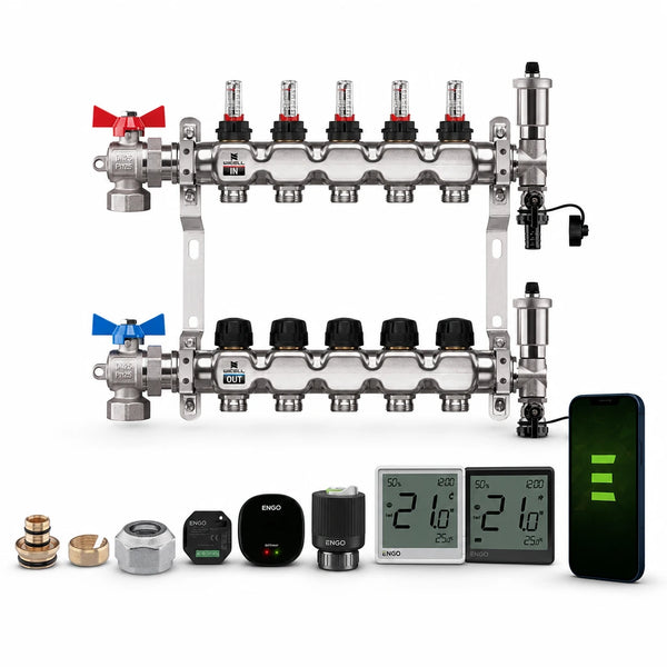
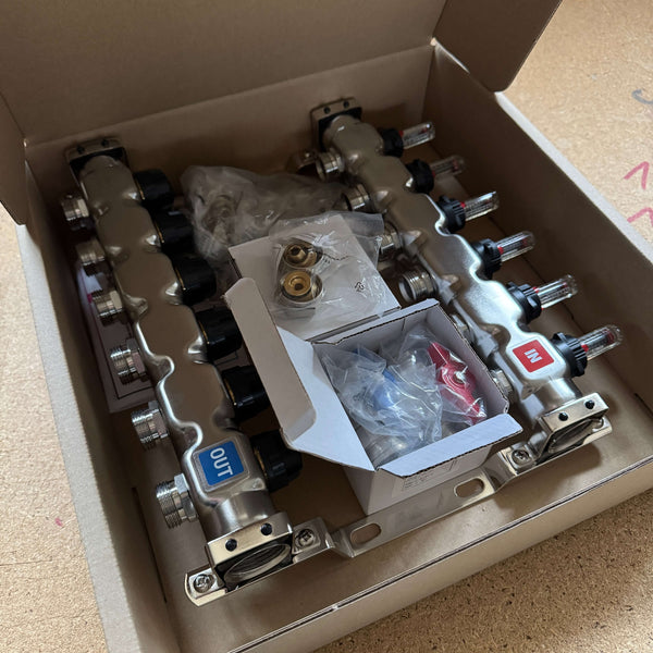
Configurable Heating Circuit Manifold Set | Underfloor Heating Set Discount
Heating circuit manifold
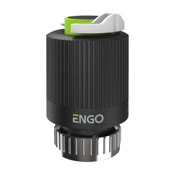
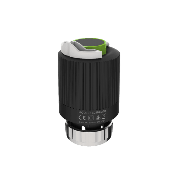
Thermoelectric actuator Engo E30NC-230 for underfloor heating
Actuator
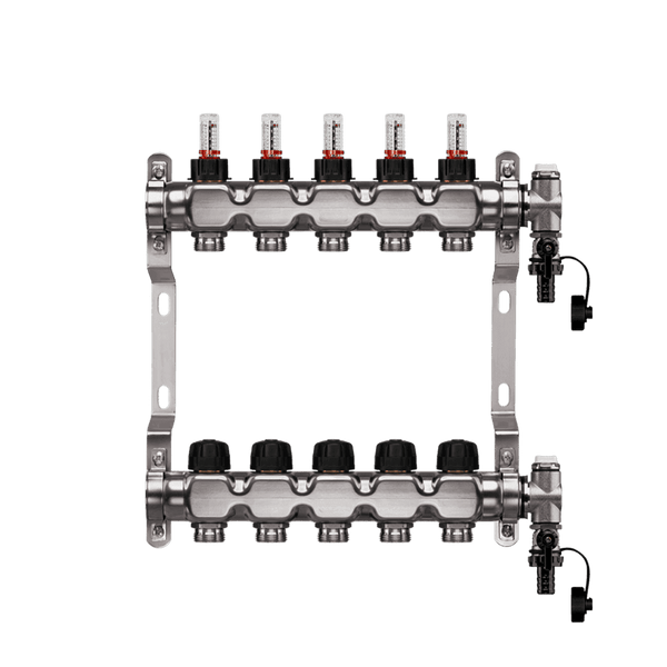
Heating circuit manifold with top meter
Heating circuit distributor
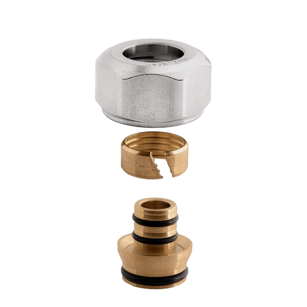
Compression ring screw connection 3/4" Eurocone
Connection screw