
Planning Fundamentals: What do I need to know?
Required Planning Information
- →Floor plan with room dimensions (in m²) – for pipe quantity and heating circuit division
- →Room heat load (W/m²) – roughly: old building 80–120 W/m², renovated building 40–80 W/m², new building 20–40 W/m²
- →Flow temperature of the heating system – heat pump: 35–40 °C, condensing boiler: 40–50 °C
- →Pipe diameter: 12 mm (small rooms, max. 70 m/circuit), 14 mm (max. 90 m), 16 mm (max. 100 m)
- →Desired spacing: 10 cm (high) / 15 cm (standard) / 20 cm (low) heat load
- →Number of heating circuits = Area ÷ max. circuit area (for 70 m pipe and 15 cm spacing: ~10 m²/circuit)
Normative Limit Values (DIN EN 1264)
- →Max. floor temperature living space: 29 °C (DIN EN 1264) – determines the maximum heating output
- →Max. floor temperature bathroom/edge zones: 35 °C
- →Spread (flow-return): 5–10 K – influences flow rate and pump performance
- →Perimeter area (0.5–1 m at outer walls + windows): Lay pipes 50% closer than in the main area
- →Buffer for bends and manifold connections: +10–15% of the calculated pipe quantity
Laying distance & pipe quantity – the three standard values
- →Installation spacing 10 cm: ~10 m pipe/m² – for high heating loads (old buildings with exterior walls, bathrooms), heat output up to 100 W/m²
- →Laying distance 15 cm: ~6.7 m pipe/m² – standard value for living areas, heat output approx. 60–80 W/m²
- →Pipe spacing 20 cm: ~5 m pipe/m² – for well-insulated rooms (KfW new build), heat output approx. 40–60 W/m²
- →Formula Pipe Quantity: (Room area × meters/m²) + edge zone surcharge + 15% buffer. Example 20 m², 15 cm: (20 × 6.7) + 10% = 147 m → 2 heating circuits
- →COP Optimization: 10 cm spacing instead of 15 cm → more uniform floor temperature → flow temperature can drop by 5–8 °C → heat pump COP increases by approx. 25–30%. For heat pump combinations, always choose the narrowest spacing that the heating load allows
Planning a Thin-Film System: 5 Calculation Steps
Step 1 – Determine heat load per room: Rough rule of thumb: Old building, unrenovated: 80–120 W/m². Old building, renovated (new windows/insulation): 50–80 W/m². KfW-55 new build: 25–40 W/m². Exact calculation according to DIN EN 12831 by the heating engineer. The heat load determines how closely you need to lay the pipes and what flow temperature is required.
Step 2 – Select flow temperature & pipe spacing: Heat pump: Flow temperature 35–40 °C → laying distance 10–15 cm recommended. Condensing boiler: Flow temperature 40–50 °C → 15–20 cm possible. Rule of thumb: The lower the flow temperature, the tighter the laying distance. Edge areas on outer walls should always be laid tighter than the inner room surface (approx. 50% higher pipe density).
Step 3 – Calculate pipe quantity: Pipe quantity (m) = room area (m²) × meters/m² (depending on spacing) × 1.15 (buffer). Edge zone: first 0.5–1 m along exterior walls should be calculated with 50% more density. Example: 15 m² kitchen, 10 cm spacing: 15 × 10 × 1.15 = 172.5 m. Since max. 70 m/heating circuit (12mm): 3 heating circuits are necessary.
Step 4 – Divide heating circuits: Maximum circuit length: 12mm pipe → 70 m, 14mm → 90 m, 16mm → 100 m. Keep circuits as equal in length as possible (±10 m) for balanced manifold distribution. Ideally, each room should have its own heating circuit (individual room control). Position the heating circuit manifold centrally in the building to minimize pipe lengths to the circuits.
Step 5 – Dimension the manifold: Manifold size = number of heating circuits. 1-2 rooms: 2-port manifold. Apartment with 3-4 rooms: 4-port. Whole house: 6-12-port. Flow rate per circuit: approx. 1.5-3 l/min (depending on pipe length and temperature spread). Plan for thermostatic flow regulators on the manifold for hydraulic balancing. Circulation pump: HVAC professional dimensions according to total volume flow.
Common Planning Questions
Formula: Room area (m²) × pipe quantity factor × 1.15 (buffer). Pipe quantity factors for MC Therm thin-layer system: 10 cm spacing = 8.8 m/m²; 12.5 cm = 6.8 m/m²; 15 cm = 5.8 m/m². Example bathroom 8 m², 10 cm spacing: 8 × 8.8 × 1.15 = 81 m pipe → 2 heating circuits (max. 70 m/circuit for 12mm pipe). Allow ~20% extra for the edge area along exterior walls.
A narrower spacing creates a more uniform surface temperature at a lower flow temperature. A heat pump operating at a flow temperature of 35 °C instead of 45 °C achieves a 25–30% higher COP (efficiency). Specifically: COP 4.5 instead of 3.5 for 1,000 kWh heating output = approx. €80 electricity savings p.a. – simply by narrowing the pipe spacing. For gas condensing boilers: 15 cm is sufficient.
For KfW-458 funding: yes, absolutely essential. The room-by-room heating load calculation according to DIN EN 12831 is a funding requirement – without it, the application will be rejected. It is also needed for the correct sizing of the heat pump and the hydraulic balancing according to method B. Costs for an energy consultant: approx. €300–700 depending on the building size. MC Therm provides a rough estimate free of charge – however, an accredited energy consultant (BAFA list) is required for official funding applications.
For the MC Therm thin-layer system: max. 70 m for 12 mm pipe, max. 90 m for 14 mm, max. 100 m for 16 mm (including flow and return to the manifold assembly). If exceeded, the pressure loss increases disproportionately: the rear part of the circuit becomes colder, the manifold can no longer balance hydraulically, and the heat pump runs inefficiently. Always keep circuits the same length (max. ±10 m difference) for stable balancing.
Suitable Products for the System
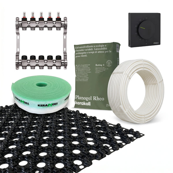
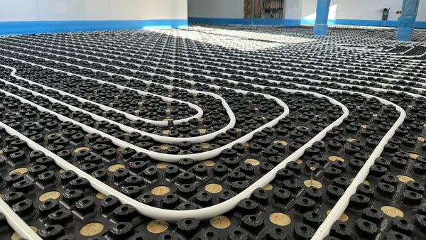
Low-Profile Underfloor Heating Complete Set | Configure your set!
Underfloor Heating Complete Set
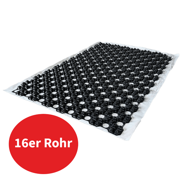
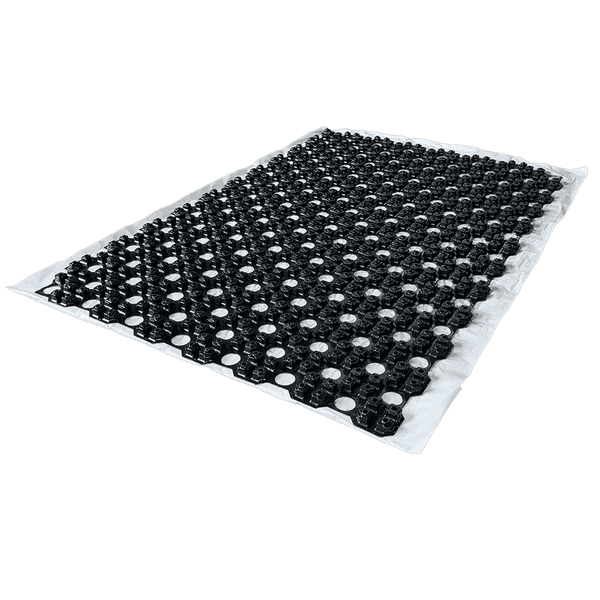
13.74 m² Thin-layer Underfloor Heating Dimpled Sheet NerthusFlow for 16mm Pipe
Bubble wrap
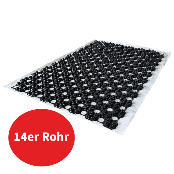
15.46 m² Thin-layer underfloor heating studded membrane NerthusFlow for 14mm pipe
Bubble wrap
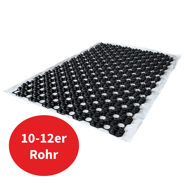
16.50 m² Thin-layer Underfloor Heating Dimpled Sheet NerthusFlow for 10-12mm Pipes
Bubble wrap