Preparation: Tools, Material & Mounting Position
Tools & Aids
- →Pipe wrench or water pump pliers (for G 1" connections)
- →PTFE thread seal tape (min. 12 layers)
- →Hand pressure pump for pressure testing (0–6 bar, integrated manometer)
- →Bleed key or flat-blade screwdriver for bleed valves
- →Spirit level (for horizontal alignment of the manifold)
- →Dowel & screws (M6, for distribution box wall mounting)
Prerequisites before assembly
- →Set manifold position: max. 20 m from boiler/heat pump, central to all heating circuits — minimizes pipe lengths and pressure loss
- →Is there a flow sensor in the supply pipe, or is one planned? (Mandatory for boiler control)
- →All underfloor heating pipes laid and accessible? Only install after screed has been laid and dried
- →Wall niche chiseled out for flush-mounted box or wall surface cleared for surface-mounted installation
- →230V power supply within reach for actuators and room thermostat cable (if desired)
Common Errors & Warnings
The installation of the heating circuit distributor is the critical interface between the boiler/heat pump and the underfloor heating system. Errors here lead to water loss, pressure drop, and, in the worst case, damage to the screed.
Return 25–45 °C
G 1"
control
Stainless steel DN 25
Ø 16–20 mm
Pipes in screed
Step-by-Step: The 8 Critical Installation Phases
| Step | Activity | Standard / Value | Common Error |
|---|---|---|---|
| 1 – Position | Install distributor box near exterior wall; minimize supply line length | VDI 6000: max. 10 m supply line | Too far from heating: unnecessary pressure losses |
| 2 – Wall Mounting | Mount box with min. 4 anchors, 100 mm depth for inspection access | DIN 18380 | Box too shallow: hoses kink |
| 3 – FL / RL Connection | Flow (red) top, Return (blue) bottom; G-1" thread with min. 8 layers of PTFE tape | VDI 6000, G 1" EN ISO 228 | Too little PTFE → micro-leak after weeks |
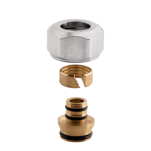
| 4 – Heating Circuit Hoses | PE-RT Ø 16 mm with Eurocone screw connection; bending radius ≥ 8×d | EN ISO 15875 | Sharp kinks at distributor outlets |
| 5 – Filling | Fill each circuit individually, open vent at distributor; system must be bubble-free | Min. 1.5 bar filling pressure | Air bubbles remain → uneven heating |
| 6 – Pressure Test | Increase pressure to 6 bar (cold test); hold for 24 h — no drop allowed | DIN EN 1264-4: 6 bar / 24 h | Only 2–4 bar tested → hidden leaks |
| 7 – Protocol | Fill out pressure test protocol (date, initial pressure, final pressure, inspector) | DIN 18560: Document for screed | No protocol → warranty issues |
| 8 – Balancing | Set flowmeter per circuit to target flow (l/h according to heat load calculation) | GModG § 60 (formerly GEG) | All circuits turned on equally → cold/warm unevenly |
Pressure Test: Values, Protocol, and Common Errors
DIN EN 1264-4
without pressure drop
in 24 hours
After the pressure test, the water must not be drained — the pressure remains in the system until the screed installation is complete. The screed layer must receive the pressure test protocol, otherwise they may reject warranty claims for screed damage.
- Pressure test protocol according to DIN 18560 is a mandatory document for the screed layer
- Without protocol: no warranty from the screed company
- Provide a copy to the construction diary and the building owner
- For renovations (GModG § 60): retain protocol as proof of efficiency measure
The 6 Most Common Installation Errors and How to Avoid Them
At least 8 layers of PTFE sealing tape on the G-1" thread. For stainless steel distributors, always combine with hemp fiber plus PTFE for permanent sealing.
Flow (red, hot) strictly at the top, return (blue, cooler) at the bottom. Reversing leads to air problems and inefficient heat distribution.
Minimum box dimensions: Width = distributor width + 10 cm, Depth = 10 cm (hose bending). Boxes that are too tight force hoses into impermissible bending radii.
Fill each circuit individually and completely vent through the bleed valve on the distributor. Residual air leads to cold spots and uneven heating.
Regional Peculiarities: Germany, Austria, Switzerland
In Germany, the Building Modernization Act (GModG) has been in effect since July 2026, replacing the former GEG. § 60 GModG mandates hydraulic balancing for all buildings with central heating supply — the pressure test and flowmeter setting at the distributor are thus a legal obligation for new installations and renovations. In Austria, OIB Guideline 6 applies, and in Switzerland, SIA 384.
- →Step 1: Fit the distribution box into the wall recess, align it horizontally, and fasten it with wall plugs
- →Step 2: Screw ball valves (flow at top / return at bottom) to manifold with PTFE sealing tape
- →Step 3: Insert manifold into the box, snap in holders
- →Step 4: Connect the underfloor heating pipes (flow and return) sequentially to the manifold connections - label the circuits!
- →Step 5: Slowly fill the system with water via the ball valve, bleeding each circuit individually
- →Step 6: Perform pressure test with manual pressure pump to 6 bar for 30 minutes — no pressure drop = sealed
- →Step 7: Screw actuators (E30NC-230) onto all manifold outlets, route cables to room thermostats
- →Step 8: Set flowmeter to target value (0.5–2.5 l/min per circuit depending on room size) and commission heating
Achtung – Fachmann empfohlen
Threaded connections without sufficient PTFE sealant tape (at least 12 layers) lead to slow leaks—especially at G 1" threaded connections.
Achtung – Fachmann empfohlen
Pressure test at 6 bar MUST be performed before closing the wall niche or before plastering — subsequent repairs are costly.
Frequent questions about heating circuit manifold installation
Stainless Steel Manifolds & Accessories
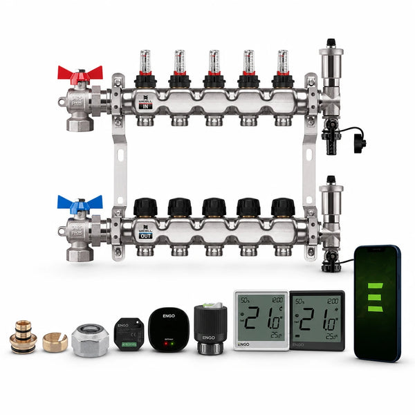
Configurable Heating Circuit Manifold Set | Underfloor Heating Set Discount
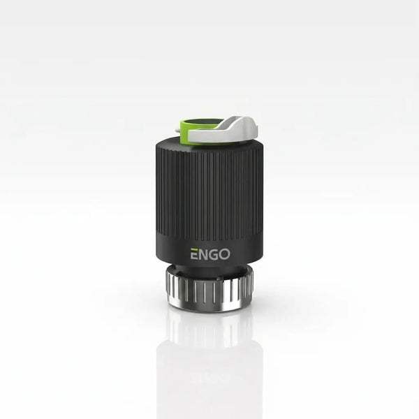
Thermoelectric actuator Engo E30NC-230 for underfloor heating
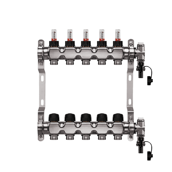
Heating circuit manifold with top meter