
Basics: Why the Number of Layers Matters
Tools & Aids
- →Pipe wrench or water pump pliers (for G 1" connectors)
- →PTFE thread seal tape (min. 12 layers)
- →Hand pressure pump for pressure testing (0–6 bar, integrated manometer)
- →Bleeding key or flat-head screwdriver for bleed valves
- →Spirit level (for horizontal alignment of the manifold)
- →Wall plugs & screws (M6, for distribution box wall mounting)
What you need to know before calculating
- →Manifold position: max. 20 m from boiler/heat pump, central to all heating circuits — minimizes pipe lengths and pressure loss
- →Flow sensor in the supply pipe present or planned? (mandatory for boiler control)
- →All underfloor heating pipes laid and accessible? Only install after screed installation and drying phase
- →Wall niche chiselled out for flush-mounted box or wall surface exposed for surface mounting
- →230V power within reach for actuators and room thermostat cables (if desired)
Calculating Circles: Tables, Formulas, and Building Types
How many heating circuits do I need for my underfloor heating? This question arises with every new build and every renovation. Too few circuits mean uneven heating; too many are unnecessary effort. The correct number of circuits depends on pipe spacing, room size, and heat load.
(15 cm pipe spacing)
PE-RT Ø 16 mm
between circuits
Number of circuits by room size: The practical table
| Room size | Pipe spacing 10 cm | Pipe spacing 15 cm | Pipe spacing 20 cm |
|---|---|---|---|
| up to 10 m² | 1 circuit | 1 circuit | 1 circuit |
| 10–16 m² | 1 circuit | 1 circuit | 1 circuit |
| 16–24 m² | 2 circuits | 1–2 circuits | 1 circuit |
| 24–35 m² (living room) | 3 circuits | 2 circuits | 1–2 circuits |
| 35–50 m² | 4–5 circuits | 3 circuits | 2 circuits |
| 50–80 m² | 6–7 circuits | 4–5 circuits | 3 circuits |
Note: For perimeter zones (external walls, glass fronts), a narrower pipe spacing (10 cm) is recommended — this increases the number of circuits. Wet rooms (bathroom, WC) should always be planned as a separate circuit.
Calculate circuit length and number of circuits: The formulas
L_pipe [m] = (Room area [m²] ÷ Pipe spacing [m]) + 2 × Supply line length [m]
2. Number of circuits:
n_circuits = ROUNDUP(L_pipe total ÷ 120)
3. Circuits per room:
n = ROUNDUP(Room area ÷ Area_per_circuit)
Factors influencing the number of circuits
| Factor | Effect on number of circuits | Recommendation |
|---|---|---|
| Pipe spacing | 10 cm → twice as many meters → more circuits needed | 15 cm standard, 10 cm for perimeter zones |
| Floor structure (screed/dry) | Dry: max. 100 m recommended; Screed: up to 120 m | Check per installation system |
| Heat source | HP: narrower spacing for more surface area → lower flow temp. | 10–15 cm for HP system |
| Room layout | Each room ideally its own circuit (individual room control) | GModG § 61 Individual room control |
| Building type | SFH: usually 5–10 circuits; Condominium: 2–5 circuits; MFH: 6–12 per floor | Heat load calculation DIN EN 12831 |
Manifold size recommendation for typical DACH building types
Typically 7–9 circuits. Recommendation: 8-circuit manifold. 1 circuit per room (living room possibly 2), 15 cm pipe spacing, PE-RT 16 mm.
Typically 4–6 circuits. Recommendation: 4- or 6-circuit manifold. Bathroom, WC, kitchen, living room, bedroom each a separate circuit.
10 cm pipe spacing due to shallow build-up → more circuits. For 80 m²: 6–8 circuits. Max. 80 m pipe length per circuit for Ø 14 mm.
Narrower pipe spacing (10 cm) for maximum heating surface → lower flow temperature → higher COP. Plan for more circuits.
- § 61 GModG (formerly § 61 GEG): Each room must be individually controllable
- Solution: One heating circuit per room + thermostat = GModG compliant
- Multiple circuits in one room without separate control: GModG violation
- Exception: Rooms under 6 m² can be controlled together
- In Austria, ÖNORM B 8130 applies, in Switzerland SIA 382 analogously
- →Step 1: Fit the distribution box into the wall niche, align horizontally, and secure with anchors
- →Step 2: Screw ball valves (flow top / return bottom) to manifold with PTFE sealing tape
- →Step 3: Insert distributor into the box, snap in the retaining clips
- →Step 4: Connect the underfloor heating pipes (flow and return) sequentially to the manifold connections – label the circuits!
- →Step 5: Slowly fill the system with water via the ball valve, bleeding each circuit individually
- →Step 6: Carry out pressure test with hand pressure pump at 6 bar for 30 minutes – no pressure drop = sealed
- →Step 7: Screw actuators (E30NC-230) onto all manifold outlets, lay cables to room thermostats
- →Step 8: Set flowmeter to target value (0.5–2.5 l/min per circuit depending on room size) and start heating
Achtung – Fachmann empfohlen
Threaded connections without sufficient PTFE sealant tape (at least 12 layers) lead to creeping leaks — especially on G 1" threaded connections.
Achtung – Fachmann empfohlen
Pressure testing to 6 bar MUST be carried out before closing the wall niche or before plastering — subsequent repairs are costly.
Frequently Asked Questions about Underfloor Heating Manifold Installation
Stainless Steel Heating Circuit Manifolds & Accessories
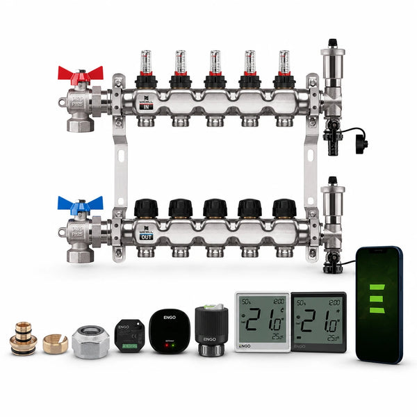
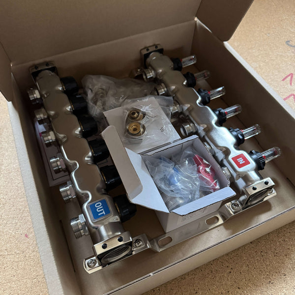
Configurable Heating Circuit Manifold Set | Underfloor Heating Set Discount
Heating circuit manifold
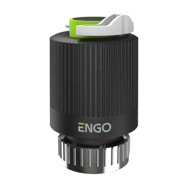
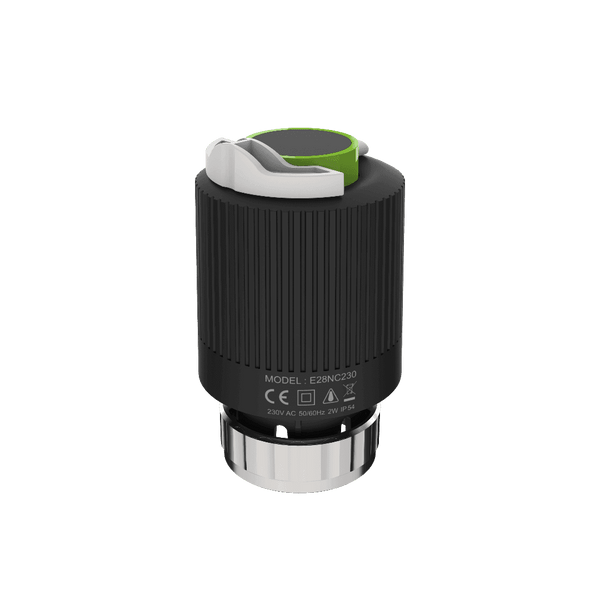
Thermoelectric actuator Engo E30NC-230 for underfloor heating
Actuator
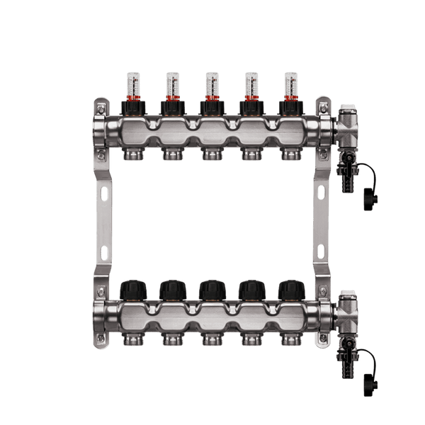
Heating circuit manifold with top meter
Heating circuit distributor
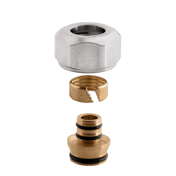
Compression ring screw connection 3/4" Eurocone
Connection screw